As explained in my previous post, the current V1.1 RedPitaya board lacks the voltage regulators for the analog output circuit which causes a number of problems such as nonmonotonic DACs, excess noise and crosstalk. If you want to equip your board with those regulators, turn on your soldering iron and enjoy the rest of the blogpost!
Planning
First you will need to decide if you want to go for positive and negative regulators or only for the positive one. Since the analog offset voltage that causes the trouble described in the previous post is only derived from the positive analog supply voltage, there is no real benefit in putting the negative regulator on the board. But I’ll describe it anyways and let you decide whether you follow my advice or not.
Needed components
The circuit schematic of voltage regulation looks like this:

The crossed-out components are what you will need to add to the board. If you do so, you also have to remove L2 (for the positive regulator) and L6 for the negative one to disconnect the digital supply from the newly created analog supply voltage. Here is where you can find these components on the bottom side of your board (the SMA-connectors point to the right of the picture):
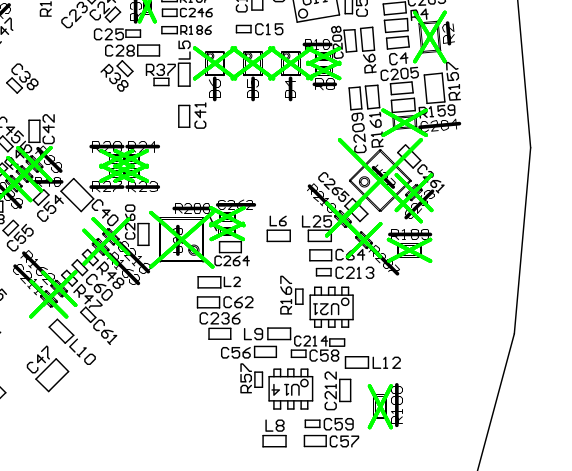
Do not get confused by all the crossed-out components in green: Only look for the components listed in the schematic above. For your convenience here is a shopping/soldering list.
Positive regulator
- U28 – positive regulator LT3082EDD – RS-code 823-0101
- R208 – 332k resistor – RS-code 678-9172
- C262 – 10pF capacitor, 50V – RS-code 435-1447 (you could try a bigger value such as 1 nF here, maybe that will improve noise performance a bit)
- we will remove: L2 – 0 ohm resistor
Negative regulator
Attention: the RS-code of the negative components is outdated. The pagage of capacitors and resistors must be 0402 and not, as the RS-codes suggest, 0603. The indicated, bigger package also works but is harder to solder because its not perfectly adapted to the board
- U27 – negative regulator LT1964EDD
- C263 – 10nF,25V capacitor – RS-code 723-5679
- R210 – 56k0 resistor – RS-code 566-935
- R207 – 33k0 resistor – RS-code 661-8745
- we will remove: L6 – 0 ohm resistor
Soldering
Once you have the components, you need to place them on the board. The resistors and capacitors should be straightforward, only the regulator is a little difficult. The regulator IC has a connector on the bottom which does not have to be connected to the pad below it for proper functioning, which makes it possible to install the component only with a soldering iron. You should first remove the residual solder from the pads on the RedPitaya board where this component will go, especially from the large center pad. Then, with some solder paste, a fine and well-heated solder iron tip and a lot of patience, you can try to connect the pads at the side of the regulator. You probably need to heat your iron to above 350 degrees Celsius to get this to work as the heat dissipation on the RedPitaya board is very good. After a successful but painful and ugly try, I actually asked an electronician of a neighbouring lab to do the solder job because it was really difficult to do it properly. Also, the regulator has 8 physical pins but only 3 different signals connected to it. So if you fail at one solder joint, it should still work.
Testing
There are two things to test after soldering:
- Is the analog voltage regulator working? Power your RedPitaya board and measure the voltage between ground (for example the outside of the SMA connectors) and the two pads of L2 (or rather where it used to be). One should be at the digital 3.3V rail voltage, the other one at the analog regulated voltage of 3.2 or 3.3 V. Following the tracks on the board or testing the continuity between the voltage regulator and those two pads when the board is unpowered makes it easy to figure out which one is which.
- Is the board working? If the green LED (a.k.a. “power good”) does not light up after your operation, don’t panic. There is a test circuit which also verifies that the negative 3.3 V analog supply voltage is correct. So if you did a mistake there, just go over it again and verify that it at the right level.
Conclusion
You should now have an improved RedPitaya V1.1 board. If you can, check whether the performance is similar to the one stated in my previous post.
Thanks
Zumy Topcagic from RedPitaya was very helpful in providing the schematics and other technical information for making this project work. Thanks also to Brigitte Delamour from the LKB and Julien Coridian from the LPNHE for helping with the soldering.

…and I’m still kinda thirsty 😉
LikeLike
Tes bieres ont disparu d’une facon mysterieuse de mon bureau.. mais je m’en occupe 🙂
LikeLike
Thanks a milion! I almost had to abandon the RP for my project after realising last week that the noise performance was not at all 14 bit standard.But with this modification things look great again. Moreover the offset is wanted in my application, which in itself already gives me one more useful bit.
LikeLike
Nice! I’m glad the modification worked for you. Thanks for the feedback.
LikeLike
Hi,
there is a little typo in the negative LDO name. It is supposed to be LT1964EDD and not LTI964EDD (1 instead of an I).
LikeLike
I just fixed it, thanks a lot for noticing!
LikeLike